Questions

Published

September 26, 2024

Potential Flow theory

  1. This question has three subparts.

    1. Derive the integral form of energy conservation equation for compressible inviscid flow in the Lagrangian framework from the basic principles. Clearly state all the assumptions underlying your equation.

    2. Convert the equation to the Eulerian framework. State the name of the theorem used to convert the Langrangian equations to the Eulerian framework.

    3. Derive the differential form of the energy conservation equation for the compressible flow case.

  2. Consider the two dimensional mass and momentum conservation equations for a compressible flow.

    1. Rewrite these equations using substantial derivative notation (\(\frac{D}{Dt}\)) in following form. There should be no substantial derivative term on the right hand side.

    2. Derive Bernoulli’s equation valid over the entire flow domain under other appropriate assumptions. Please mention all the assumptions, theorems and logical arguments used during the derivation.

    3. List all the assumptions under which these equations are valid.

    4. Derive Bernoulli’s equation valid over a streamline under other appropriate assumptions. Please mention all the assumptions, theorems and logical arguments used during the derivation.

\[\begin{aligned} \frac{\partial \rho}{\partial t} + \nabla \cdot (\rho \bar{U} ) & = & 0 \\ \frac{\partial (\rho u)}{\partial t} + \nabla \cdot (\rho u \bar{U} ) & = & - \frac{\partial p}{\partial x} \\ \frac{\partial (\rho v)}{\partial t} + \nabla \cdot (\rho v \bar{U} ) & = & - \frac{\partial p}{\partial y} \\ \end{aligned}\]

  1. Compressible flow equations for inviscid flow are given by:

\[\frac{D \rho}{D t} + \rho \nabla \cdot \bar{U} = 0,\ \ \frac{D \bar{U}}{D t} + \frac{1}{\rho} \nabla p = 0,\ \ \frac{D e_t}{D t} + \frac{1}{\rho} \nabla \cdot (p\bar{U}) = 0\]

Here \(e_t = e + |\bar{U}|^2/2\). Derive the expression for \(\frac{D e}{D t}\) using above equations. Using this expression, what can we say about the internal energy and temperature of an incompressible flow.

  1. Express the equations for an ideal fluid in terms of streamline coordinates.

  2. Show that, the uniform flow is irrotational in nature and it is physically possible for an incompressible flow.

  3. Show that the three-dimensional source flow is irrotational.

  4. A source of strength \(25\,m^3 s^{−1}\) and a sink of equal strength are placed \(2\,m\) apart on the x-axis. If an uniform flow of velocity \(50\,m/s\) in negative x-direction is superimposed on this source–sink combination, then calculate the size of the Rankine oval body thus formed.

  5. What will be the shape of the streamlines, if the freestream velocity of the flow over a circular cylinder is doubled? Discuss both the inviscid and viscous flow conditions.

  6. Derive the equation of streamlines for which the tangential velocity is \(A r\) and the radial velocity component is \(\theta\). \(A\) is a constant.

  7. A Laplace equation is given by

\[\nabla^2 \phi = 0,\ \text{with BCs}\ \nabla \phi_{wall} \cdot \hat{n}_{wall} = 0,\ \text{and}\ \nabla \phi_{\infty} = 0\]

Suppose \(\phi_1 = x^2 − y^2\) and \(\phi_2 = r^{1/2} \cos{(\frac{\theta}{2})}\) are the solutions of this Laplace equation. Prove that their linear combination, i.e., \(\phi_3 = \omega_1\phi_1 + \omega_2 \phi_2\) satisfies the Laplace equation as well. \(\omega_1\) and \(\omega_2\) are some arbitrary constants.

  1. What are the minimum and maximum values of the coefficient of pressure on a nonrotating circular cylinder in an uniform freestream when \(k = 4 \pi U_\infty\).

  2. Estimate the circulation around a circular cylinder with radius \(0.1\,m\) when it is placed in an uniform flow of velocity \(U_\infty = 3\,m/s\), which has the lift coefficient \(C_L=0.4\).

  3. Determine the radius of vortex flow having tangential velocity \(u_\theta=16\,m/s\) and circulation \(8\,m^2/s\).

  4. List the flow properties required to describe the state of flow at a point for a three dimensional a) inviscid compressible flow, b) inviscid incompressible flow and c) inviscid irrotational incompressible flow.

  5. Show that for a potential flow over a 2D cylinder, \(C_p = 1 - 4\sin^2{\theta}\). Here origin is placed at the center of the cylinder. Also \(\theta\) is measured from X axis.

  6. Derive the expression for lift and drag using the \(C_p\) expression given above.

  7. State D’Alembert’s paradox.

  8. Is D’Alembert’s paradox also observed for a 3D flow.

  9. An aerodynamicist is willing to accept an error of 1% in her analysis of incompressible flow. She is dealing with a body with a length scale of 1m. Should she include the gravity term in the Bernoulli’s equation? It is expected that the velocity field for the phenomenon under investigation will be in the range of 0 m/s to 100 m/s under standard sea level conditions. A quantitative justification is expected here. Qualitative arguments will not fetch any marks.

  10. Show that the stream lines and the velocity potential contours are orthogonal to each other at every point in the flow domain.

  11. Is the doublet flow irrotational? Equation for the doublet flow is \[\phi = \frac{\kappa}{2\pi} \frac{\cos{(\theta)}}{r}\]

  12. Ignoring the viscous effects results in simpler equations of motion for fluid. What justifies the use of such equations for calculating the lift over an airfoil/wing?

  13. Can vorticity be defined for a point in the flow field in a way density is defined?

  14. Show that the vorticity along a streamline remains constant.

  15. Prove that circulation \(\Gamma\) is constant for a Lagrangian closed loop for a barotropic fluid.

  16. A two-dimensional velocity field is described in terms of its Cartesian components as \(u=x^2 y\) and \(v=-x y^2\). Write the equation of the streamline passing the point \((1,2)\).

\[ \begin{aligned} & \text { For two-dimensional velocity field }\frac{d x}{u}=\frac{d y}{v} \\ & \Rightarrow \quad \frac{d x}{x^2 y}=\frac{d y}{-x y^2} \\ & \frac{d x}{x}=\frac{d y}{-y} \\ & \ln x=\ln \left(\frac{1}{y}\right)+\ln C \\ & x=\frac{c}{y} \\ & \Rightarrow x y=c \end{aligned} \] for streamline passing through \((1,2)\) \[ c=2 \] \(\therefore\) Equation of Streamline passing through \((1,2)\) is \(x y=2\) or \(x y-2=0\).

Airfoil

  1. For a symmetric airfoil, thin airfoil theory equation is \(\frac{1}{2\pi} \int_0^\pi \frac{\gamma(\theta)\sin{\theta} d\theta}{\cos{\theta} - \cos{\theta_0}} = U_\infty \alpha\)

    1. Show that \(\gamma(\theta) = 2\alpha U_\infty \frac{1 + \cos{\theta}}{\sin{\theta}}\) is a solution of this equation.

    2. Show that this vortex sheet satisfies the Kutta condition.

    3. Derive the expression for lift (\(L'\)) of the airfoil using above solution and also calculate \(C_{l_\alpha}\)

    4. What is the drag (\(D\)) on the airfoil and what is the pitching moment about the quarter chord (\(M_{c/4}\)). No need for derivation. Simply state the answer for this part.

  2. An irrotational flow can have a non-zero circulation. True or False. Please give a brief justification stating any arguments/theorems that support your answer. Answers without justification will not be graded.

  3. Consider a singly connected domain of incompressible potential flow.

    1. Write down the differential equation governing this flow along with the appropriate boundary conditions.

    2. Using Divergence theorem and the equation written in the earlier part, show that the velocity potential is only defined to within a constant for this domain.

  4. Determine the radius of vortex flow having tangential velocity \(v_\theta = 16\ m/s\) and circulation \(8\ m^2/s\)?

  5. List the components of the drag on an airfoil because of viscosity. Also outline briefly how viscosity causes these components of drag.

  6. State the Kutta condition for an airfoil.

  7. Derive the mathematical statement of the Kutta condition in terms of the strength of the vortex sheet \(\gamma(s)\) for an airfoil with finite angle trailing edge.

  8. Derive the mathematical statement of the Kutta condition in terms of the strength of the vortex sheet \(\gamma(s)\) for an airfoil with cusp trailing edge.

Wing

  1. Using Biot-Savart law, show that the velocity induced by an infinite rectilinear line vortex is \[ \| \bar{U}_P \| = \frac{-\Gamma}{2\pi h} \]

where \(h\) is the distance of point P from the line vortex.

  1. Draw a plot of \(C_L\) Vs. \(\alpha\) curve for a rectangular wing as the aspect ratio (\(AR\)) of the wing is varied keeping the area of the wing fixed. Draw the curves for at least three different . Assume that the wing does not have any aerodynamics or geometric twist. Also the airfoil is cambered.

  2. A vortex panel code gives the vortex density (\(\gamma_i, i\in[1,N]\)) at \(N\) discrete panels at the end of the solution process. Write an expression for lift (\(L\)) in terms of \(\gamma_i\). Clearly define any other variables in the formula.

  3. If \(C_{l_\alpha}\) and \(C_{m_\alpha}|_{(c/4)}\) are known, how do I calculate the location of the aerodynamic center (\(\bar{x}_{ac} = x_{ac}/c\))?

Boundary Layer

  1. Plot \(y\) Vs. \(U\) for a fully developed laminar and turbulent boundary layer. The variable \(y\) denotes the distance along the local normal direction to the wall. Draw a single plot for both types of boundary layers. Also clearly mark \(U_\infty\) on \(U\) axis.

  2. What is a critical Reynolds number in the context of boundary layers? How is it determined?

  3. An airfoil has \(Re_c = 3.1 \times 10^6\) where \(Re_c\) is the Reynolds number corresponding to the chord of the airfoil. Critical Reynolds number is \(Re_{cr} = 5 \times 10^5\). Calculate the net skin friction drag coefficient for the airfoil.

  4. Shear stresses on a flat plate are higher in the region with turbulent boundary layer than the laminar boundary layer. Why?

  5. Critical Reynolds number is higher for laminar boundary layers than the turbulent boundary layers. True/False. Explain.

  6. A pylon structure that houses a camera is to be designed for a UAV. The vehicle operates under conditions at which a laminar or a turbulent boundary layer can be achieved depending on the surface roughness of the pylon. The contribution of the pylon to the overall lift is negligible. Which type of boundary layer is preferable? Assume the pylon to have aerodynamic shape. It is not be considered as a bluff body.

  7. Critical Reynolds number of a UAV airfoil was determined experimentally in a wind tunnel to be \(420000\) at \(U_\infty = 30\,m/s\) and sea-level standard atmospheric conditions. A test flight conducted at \(U_\infty = 20\,m/s\) at sea-level standard atmospheric conditions was conducted to investigate the nature of boundary layer on the wing. If turbulent boundary layer was observed during the flight, give at least three possible reasons that explains this discrepancy.

  8. Explain mechanism of aerodynamic heating.

  9. Aerodynamic heating for a turbulent boundary layer is higher than the laminar boundary layer. True/False? Explain.

  10. Reliable estimation of wave drag and the induced drag is possible using inviscid flow models. True/False. Explain.

  11. What are the dimensions of dynamic viscosity coefficient (\(\mu\)) and thermal conductivity (\(k\))?

  12. Shear stress \(\tau_{xy}\) acts in direction X and is being exerted on a plane perpendicular to the Y axis. True/False.

Delta Wing

  1. Draw the \(C_p\) variation along the span of a delta wing at quarter chord, mid-chord and full-chord locations on a single plot.

  2. Draw \(C_L\) vs. \(\alpha\) plot for a high aspect ratio wing made from a thin symmetric airfoil. Also draw the same plot for a delta wing made from the same airfoil. Both plots should be on the a single graph.

  3. What is vortex lift? Explain the generation of vortex lift over delta wing.

  4. It is known that vortex lift accounts partially for the total lift generated by a delta wing. Why traditional (high aspect ratio) wings do not use vortex lift to increase the overall lift generation.

  5. It is found that delta wings are usually made from a very thin airfoil with a sharp leading edge. Why is that?

  6. Write a short note on two ways to increase the \(L/D\) of a delta wing.

High Lift Devices

  1. Draw \(C_L\) Vs. \(\alpha\) plot for an airfoil with a trailing edge flap. Draw the plot for \(\delta=0\), \(\delta_1 > 0\) and \(\delta_2 > \delta_1\). Here \(\delta\) is the flap angle.

  2. At low incidence angles, increase in drag because of a trailing edge flap is desirable. True or false. Please give an explanation.

  3. Center of pressure moves forward with the deployment of a trailing edge flap. True or false. Please give an explanation.

  4. Plot \(C_L\) Vs \(C_D\) on a single axis for

  • plain wing
  • wing with plain flap
  • wing with split flap
  • wing with fowler flap
  1. Write a short note on how a leading edge slat works. Draw a \(C_L\) Vs. \(\alpha\) diagram for the slat.

Applications

  1. A pitot tube on an airplane flying at standard sea level reads \(1.07 \times 10^5 \mathrm{~N} / \mathrm{m}^2\). What is the velocity of the airplane?

At standard sea level,

\[ \begin{aligned} \rho_{\text {SSL }} & =1.225 \mathrm{~kg} / \mathrm{m}^3 \text { (density) } \\ P=P_{\text {SSL }} & =1.01325 \times 10^5 \mathrm{~N} / \mathrm{m}^2 \text { (pressure) } \end{aligned} \]

Pitot tube measures the stagnation pressure. \[ \begin{gathered} P_{\text {stag }}=P+\frac{1}{2} \rho V^2 \\ P_{\text {stag }}=1.07 \times 10^5 \mathrm{~N} / \mathrm{m}^2, \rho=\rho_{\text {SSL}}=1.225 \mathrm{~kg} / \mathrm{m}^3 \text { and } \\ P=P_{\text {SSL }}=1.01325 \times 10^5 \mathrm{~N} / \mathrm{m}^2 \end{gathered} \]

Putting these values, \[ \begin{aligned} & 1.07 \times 10^5=1.01325 \times 10^5+\frac{1}{2}(1.225) v^2 \\ & \frac{5675(2)}{1.225}=v^2 \\ & \Rightarrow \quad v=96.256 \mathrm{~m} / \mathrm{s} \end{aligned} \]

The velocity of airplane is \(96.256 \mathrm{~m} / \mathrm{s}\)

  1. Consider a low-speed open-circuit subsonic wind tunnel with an inlet-to-throat area ratio of 12 . The tunnel is turned on, and the pressure difference between the inlet and the test section is read as a height difference of \(10 \mathrm{~cm}\) on a \(U\)-tube mercury manometer. Calculate the velocity of the air in the test section. \(\rho_{\mathrm{Hg}}=1.36 \times 10^4 \mathrm{~kg} / \mathrm{m}^3\).

\[ \frac{A_i}{A_t}=12, \Delta h=10 \mathrm{~cm} \]

Using continuity equation, \(\quad A_i V_i=A_t V_t\) (low speed, so incompressible)

\[ V_i=\left(\frac{A_t}{A_i}\right) V_t=\frac{V_t}{12} \cdots \text {(1)} \]

Using Bernoulli’s theorem, (between inlet & test section) \[ \begin{aligned} & P_i+\frac{1}{2} \rho_a V_i^2=P_t+\frac{1}{2} \rho_a V_t^2 \quad(\text { assuming no losses, and } \\ & z=\text { constant }) \\ & P_i-P_t=\frac{1}{2} \rho_a\left[V_t^2-V_i^2\right] \\ & \rho_{\text {Hg }} g(\Delta h)=\frac{1}{2} \times 1.225\left[V_t^2-\frac{V_t^2}{144}\right] \ldots(\text { from (1) )} \\ & (13600)(9.8)\left(\frac{10}{100}\right)=\frac{1}{2} \times 1.225 \times \frac {143}{144} V_t^2 \\ & \Rightarrow V_t^2=\frac{(13600)(9.8)(0.1)(2)(144)}{(1.225)(143)} \\ & \Rightarrow V_t=148.027 \mathrm{~m} / \mathrm{s} \end{aligned} \]

So, the velocity of air in test section is \(148.027 \mathrm{~m} / \mathrm{s}\).

  1. An aircraft (with rectangular wing) is cruising at \(U_\infty = 50\ m/s\), \(W/S = 1000\ N/m^2\), and the thurst is \(T = 100\ N\). Given that the boundary layer transitions at \(c/4\) for the wing, estimate the pressure drag coefficient for the aircraft. The wing has an aspect ratio of 10 and \(c = 2\ m\). Assume elliptical lift distribution over the wing. Data: \(\rho_\infty = 1.225\ kg/m^3\). \(\mu_\infty = 1.789 \times 10^{-5}\ N/m^2\). Assume that all the drag contribution to the aircraft is coming from the wing and the contribution of the fuselage and other systems is negligible.
Code
wbys = 1000              # N/m^2
ρ∞ = 1.225               # kg/m^3
U∞ = 50                  # m/s
q∞ = 0.5 * ρ∞ * U∞^2
CL = wbys/q∞
AR = 10
CDᵢ = CL^2/π/AR
c = 2                     # m
μ∞ = 1.789 * 10^-5        # N/m^2
Re_cr = ρ∞*U∞*c/4/μ∞
Re_c = 4 * Re_cr
CDₛ = 2* ( (1/4)*1.328/sqrt(Re_cr) + 0.074/Re_c^0.2 - (1/4)*0.074/Re_cr^0.2 )
b = AR*c                 # m1
S = b*c                  # m^2
T = 100                  # N
CDₚ = T/(q∞*S) - CDᵢ - CDₛ
display("Induced drag coefficient is $(round(CDᵢ, digits=4))")
display("Skin friction drag coefficient is $(round(CDₛ, digits=4))")
display("Pressure drag coefficient is $(round(CDₚ, digits=4))")
"Induced drag coefficient is 0.0136"
"Skin friction drag coefficient is 0.0048"
"Pressure drag coefficient is -0.0167"

We can see in this example that the induced drag coefficient \(C_{D_i}\) is the largest component followed by the skin friction drag. Since pressure drag is the smallest component, this means that there is no flow separation and the flow is attached.

  1. An aircraft (with rectangular wing) is cruising at \(U_\infty = 50\ m/s\), \(W/S = 1000\ N/m^2\), and the thurst is \(T = 100\ N\). Given that the boundary layer transitions at \(c/4\) for the wing, estimate the pressure drag coefficient for the aircraft. The wing has an aspect ratio of 10 and \(c = 2\ m\). Assume that all the drag contribution to the aircraft is coming from the wing and the contribution of the fuselage and other systems is negligible. Assume elliptical lift distribution over the wing. Data: \(\rho_\infty = 1.225\ kg/m^3\). \(\mu_\infty = 1.789 \times 10^{-5}\ N/m^2\).
Code
wbys = 1000              # N/m^2
ρ∞ = 1.225               # kg/m^3
U∞ = 50                  # m/s
q∞ = 0.5 * ρ∞ * U∞^2
CL = wbys/q∞
AR = 10
CDᵢ = CL^2/π/AR
c = 2                     # m
μ∞ = 1.789 * 10^-5        # N/m^2
Re_cr = ρ∞*U∞*c/4/μ∞
Re_c = 4 * Re_cr
CDₛ = 2* ( (1/4)*1.328/sqrt(Re_cr) + 0.074/Re_c^0.2 - (1/4)*0.074/Re_cr^0.2 )
b = AR*c                 # m1
S = b*c                  # m^2
T = 100                  # N
CDₚ = T/(q∞*S) - CDᵢ - CDₛ
display("Induced drag coefficient is $(round(CDᵢ, digits=4))")
display("Skin friction drag coefficient is $(round(CDₛ, digits=4))")
display("Pressure drag coefficient is $(round(CDₚ, digits=4))")
"Induced drag coefficient is 0.0136"
"Skin friction drag coefficient is 0.0048"
"Pressure drag coefficient is -0.0167"
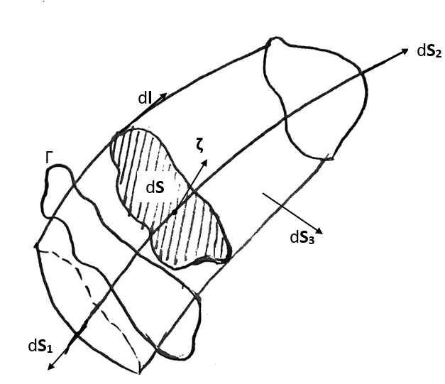
  1. Prove that circulation \(\Gamma\) is constant for a Lagrangian closed loop in a barotropic inviscid flow.

Refer notes.

  1. Define a line vortex and a vortex line.
Vortex line

The line tangential to the vorticity vector at all points is called the vortex line.

\[ U \ \ \Rightarrow \ \ \text{Stream line}\] \[ \chi \ \ \Rightarrow \ \ \text{Vortex line}\]

Line Vortex

A vortex tube can be constructed using a bunch of vortex line. If a vortex tube is replaced with a line joining the centroids of each cross-section of the vortex tube while keeping the circulation around each section constant, then a line made of thses centroids is called a line vortex. The vorticity is infinite on a line vortex but it has the same circulation as the original vortex tube.

  1. Potential flow is governed by \(\nabla^2 \phi = 0\) equation where \(\phi\) is the velocity potential. State the boundary conditions for this PDE for a flow over an airfoil.

\[ \nabla \phi_{\infty} = U_\infty\]

\[ \nabla \phi_{wall} \cdot \hat{n}_{wall} = 0\]

where, \(\hat{n}_{wall}\) is the unit normal to the airfoil surface.

  1. According to the thin airfoil theory, flat plate has higher \(C_l\) than NACA0012 airfoil (which is symmetric) at angle \(\alpha = 3^o\). True/False. Answer without an explanation will not be graded.

Thin airfoil theory works with the camberline as the representation of the airfoil. For a symmetric airfoil, this is same as chordline. Hence, all the symmetric airfoils will have the same aerodynamics characteristics as a flat plate. Hence false.

This might seem counter intuitive. In real life, as the angle of attack increases, the flow separates separates very early on from the leading edge of a flat plate. If an airfoil is thicker, then the leading edge flow separation is delayed and hence we see a difference in the aerodynamic performance of flat plate and other symmetric airfoils. Since thin airfoil theory does not capture these effects, it sees all the symmetric airfoils as sinmply a flat plate.

  1. State Kutta condition.
  1. The coefficient of pressure over a cylinder is given as \(C_p = 1 - 4\sin^2{\theta}\). Here origin is placed at the center of the cylinder and \(\theta\) is measured from X axis. Draw \(\theta\) versus \(C_p\) diagram. On the same graph, also draw the actual \(C_p\) variation as observed in the wind tunnel (were we to perform an experiment). Only the trend is expected.
  1. A vortex panel code gives the vortex density (\(\gamma_i, i\in[1,N]\)) at \(N\) discrete panels at the end of the solution process. Write an expression for lift (\(L\)) in terms of \(\gamma_i\). Clearly define any other variables in the formula.

Kutta Joukowski theorem states that

\[L = \rho_\infty U_\infty \Gamma\].

Since the total circulation can be calculated as the summation of the circulation from all panels,

\[L = \rho_\infty U_\infty \sum_{i=1}^N \gamma_i\, l_i\]

where \(l_i\) is the length of the \(i^{th}\) panel.

  1. If \(C_{l_\alpha}\) and \(C_{m_\alpha}|_{(c/4)}\) are known, how do I calculate the location of the aerodynamic center (\(\bar{x}_{ac} = x_{ac}/c\))?

For a general point \(x\),

\[C_m(x) = C_{m_{c/4}} + (x-c/4)C_l\]

where, \(C_{m_{c/4}} = C_{m_{0, c/4}} + C_{m_{\alpha, c/4}}\, \alpha\) and \(C_l = C_{l_0} + C_{l_\alpha}\, \alpha\).

Therefore, \[C_m(x) = C_{m_{0, c/4}} + C_{m_{\alpha, c/4}}\, \alpha + (x-c/4)\,(C_{l_0} + C_{l_\alpha}\, \alpha)\]

Differentiating wrt \(\alpha\),

\[ \frac{\operatorname{d}C_m(x)}{\operatorname{d}\alpha} = C_{m_{\alpha, c/4}} + (x-c/4)\,C_{l_\alpha}\]

For the aerodynamic center,

\[ \frac{\operatorname{d}C_m(x_{ac})}{\operatorname{d}\alpha} = 0\]

which leads to

\[ \bar{x}_{ac} = \frac{1}{4} - \frac{C_{m_{\alpha, c/4}}}{C_{l_\alpha}}\]
  1. An airfoil has zero-lift angle of attack of \(\alpha_{0_a}\). A zero geometric twist rectangular wing made of this airfoil has the zero-lift angle-of-attack \(\alpha_{0_w}\). What is the relationship between these two \(\alpha_0\)’s. Answer without explanation will not be graded.

The difference between the aerodynamic characteristics of an airfoil and a wing arrise primarily from the effect of the wing tip vortices. At zero lift condition, there are no wing tip vortices. Also it is given that the wing does not have any geometric twist.

Hence, \(\alpha_{0_a} = \alpha_{0_w}\).

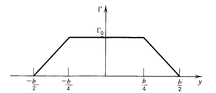
  1. If the load distribution on a finite-span wing is as shown, sketch the trailing vortex system, indicating the magnitude and direction of the trailing vortices.
  1. Plot the variation of the downwash velocity (\(U_z\)) as a function of y (coordinate along the span) for a rectangular wing with constant airfoil section. Only a rough plot with the trend is expected.
  1. What is ground effect? How does it affect the overall lift of the aircraft?

Because of the proximity of the ground, the flow pattern around the wing changes. It results in weakend wing tip vortices. This results in increased lift and reduced induced drag. This is called the ground effect.

The increase in the lift is beneficial during the take-off and landing phase.

Here, proximity means the distance between the wing and the ground is of the order of the wing span.

  1. If \(Re_c < Re_{cr}\) then the boundary layer on the airfoil is laminar. True/False. Answer without an explanation will not be graded. Here, \(Re_c\) is the Reynold’s number at the trailing edge and \(Re_{cr}\) is the critical Reynold’s number.

\(Re_c < Re_{cr}\) is only a necessary condition for laminar BL and not the sufficient condition. One can have a turbulent BL at \(Re < Re_{cr}\) if a disturbance is added to the flow in the form of a rough surface patch or wire trippers.

Hence my answer is false.

  1. We are designing an airfoil for a glider. The design team is split into two opposing groups. First group wishes to have a laminar boundary layer over the entire airfoil while the second group wishes to have turbulent boundary layer over the airfoil. Which group do you support and why?

A glider is expected to fly at low Mach numbers. Also, they usually operate at low angles of attack. Hence, the drag of a glider is mostly made up of induced drag, skin friction drag and a very small percentage of pressure drag (since low \(\alpha\)). So the over riding concern for the design team is to reduce the induced drag and the skin friction drag. BL does not play any role in the induced drag reduction while we know that laminar BL results in lower skin friction drag.

I support laminar group.

  1. Draw the laminar and turbulent boundary layer velocity profiles on the same graph so that their relative variation can be compared. Assume that they have the same boundary layer thickness.

The key difference in the profiles is that \(\frac{\partial u}{\partial y}\) is larger for the trubulent BL than the laminar BL. This is because the turbulent flow is lot of efficient at mixing flows and hence energy transfer from the outer layers of the BL increases the velocity of the flow closer to the wall as compared with the laminar boundary layer. Also, turbulent BL is lot more thicker than the laminar BL.

  1. Why are delta wings not preferred for the civilian transport aircraft like Boeing 747?

The delta wing has a lower lift to drag ratio compared to a high aspect ratio wing. This is because the delta wing has a lower aspect ratio compared to a straight wing. The higher aspect ratio results in a lower induced drag thereby resulting in fuel savings. Hence, delta wings are not preferred for civilian transport aircraft like Boeing 747.

  1. We know that supersonic fighter aircraft like the F-16 have delta wings. The primary reason for this is the sweep angle of the delta wing that results in reduction of the effective Mach number as seen by the wing. However, there is a secondary aerodynamic advantage of the delta wing for the F-16. What is this advantage?

The delta wing stalls later compared to a straight wing. This is because the vortex lift generated by the delta wing is more effective at higher angles of attack compared to a straight wing. This is useful during dogfights where the aircraft has to maneuver at high angles of attack.

  1. Draw a sketch of the primary and secondary vortex generated by a delta wing. Clearly mark the primary and secondary vortex.
  1. Center of pressure moves forward with the deployment of a trailing edge flap. True or false. Please give an explanation.

When the trailing edge flap is deployed, the \(C_p\) variation on the airfoil looks as shown in the diagram. As can be seen from the diagram, an increased pressure differential is created towards the aft of the airfoil which results in the center of pressure moving backward. Hence, the statement is false.

  1. Draw the lift coefficient vs angle of attack curve for an airfoil with and without a leading edge flap. Clearly mark the stall angle of attack for both cases.
  1. What is the difference between the leading edge flap and the leading edge slat?

The leading edge flaps delay the leading edge stall by reducing the maximum local curvature entoured by the flow over the leading edge. This is achieved by rotating the flap towards the \(U_\infty\).

On the other hand, slats delay the leading edge stall by energising the boundary layer with a fresh flow injection because of the gap between the airfoil and the slat as shown in the figure.